Flexible Printed Circuits (Flex PCBs) – What Software is Used for Designing Flexible PCBs?
What Software is Used for Designing Flexible PCBs
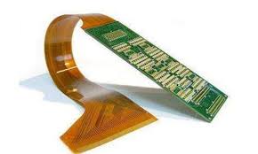
Using flexible printed circuits (flex PCBs) allows for the creation of electronic devices that are lighter and smaller than those designed with rigid copper or metal wires. However, these devices are not without challenges and need to be created with careful design considerations.
Fortunately, the right PCB software can help eliminate the need for physical prototypes and speed up the design process. By incorporating interactive routing, schematic capture, and component libraries, these design tools provide an efficient way to get a flex or rigid-flex design from concept to final product.
In order to design a flex or rigid-flexible printed circuit, it is important to decide up front how the device will be used and what flexing capabilities are needed. This will guide you in choosing a substrate material, the number of layers, and the type of copper (RA or ED). Additionally, it is also essential to consider the coverlay, adhesive, and stiffener materials that are required.
Flexible Printed Circuits (Flex PCBs) – What Software is Used for Designing Flexible PCBs?
For example, if the device is to be used in a static position with no flexing, then you can use fewer layers and less expensive coverlay materials. However, if the flex will need to be dynamic, you will need a thicker substrate with more copper layers and a more advanced stiffener material.
Once you have determined the necessary materials and flex PCB layout, it is time to begin designing the traces and routing. For this step, you will need to utilize a CAD tool that is capable of handling complex layouts and multilayer designs. This software will also need to support the generation of Gerbers and ODB++ files for fabrication. By utilizing these features, you can reduce your design time and ensure that the final product is manufacturable as intended.
Some popular flex PCB software options include KiCad, OrCAD, and PADS. All three software programs offer an extensive set of tools, but each has its own advantages and disadvantages. For example, KiCad is free and offers a simple user interface. However, it does not have the robust capabilities that other commercial flex PCB software provides. OrCAD is more expensive, but it provides a high-end user experience and includes advanced simulation capabilities. PADS is a popular choice among mid-sized companies due to its reliability, ease of use, and extensive component libraries.
A newcomer to the flex PCB market, Fusion 360, has a unique feature that lets designers preview their designs in 3D from any angle. This enables them to better understand how the design will fit inside its casing and reduces the need for costly and time-consuming physical prototypes.
Altium Designer is another popular flex PCB software option with advanced features like 3D modeling, simulation, and electrical routing. Its unified design environment makes it a great choice for professionals and large corporations. Additionally, it offers a streamlined workflow and supports collaboration with other designers across teams. Its disadvantages include a steep learning curve and expensive licensing fees.